| Installation/Work
Photos:
Take a look at the following series of
photos:
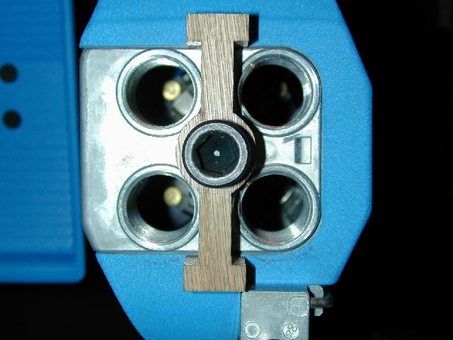
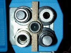
Above is a top view of the version 1+
clamp installed on a modified tool head with no dies installed. Below is
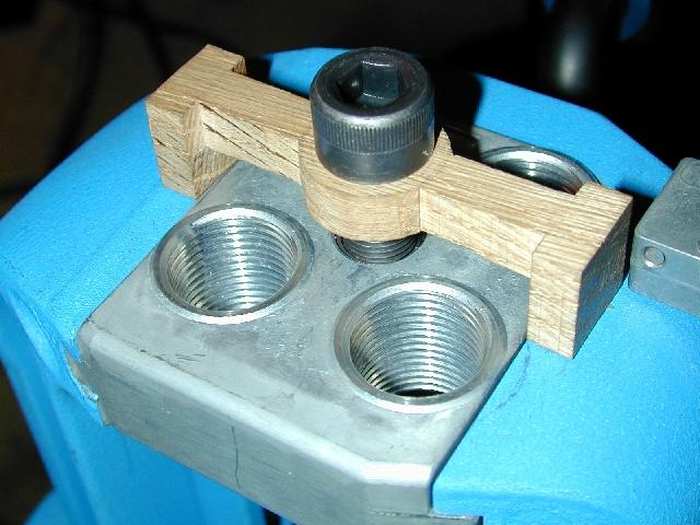
an oblique view:
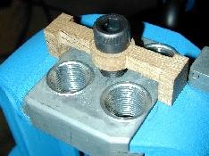
No interference with the primer system or
the tool head...Now, add the dies:
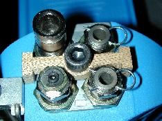
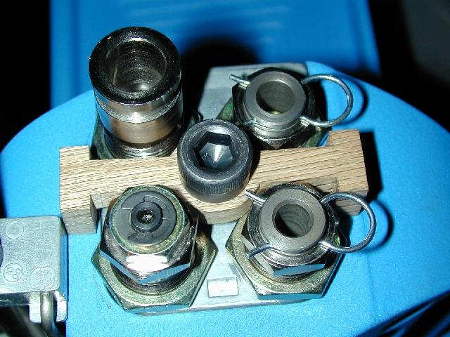
Above, is version 1+ of the clamp
installed on the tool head with a set of Dillon 40 S&W dies. Note
the "close" fit between the Dillon die insert pins and the
clamp's "ears" in this
version.
|
|
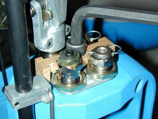
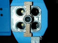
Below, is a final image of version 1+
with all components installed:

Note that the powder measure system is
installed with no interference with the fastener and unobstructed access
to the clamp fastener for adjustment. Finally, take a look at the version
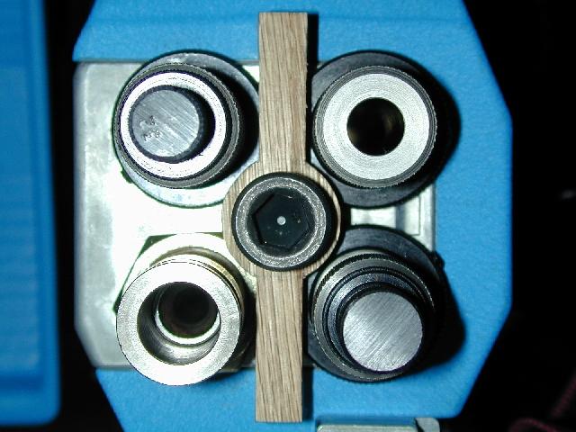
3 prototype clamp installed:
Remember, version 3 of the clamp design
deleted the "ears" from the clamp ends. Notice the increased
clearance around the die body lock rings. In the image above, a set of
Redding Pro Series Titanium Carbide dies and Redding die-body lock rings
are installed with the Dillon powder die and lock ring. I also checked
vertical fit with Forster Cross-Bolt lock rings. The Forster part is
slightly thicker than either the Redding or Dillon rings. Though there was
still sufficient vertical clearance to adjust the dies, I increased the
clamp "leg" dimension to add some breathing room" for
easier adjustment with the Forster rings. This new dimension is incorporated into version 3+ and
higher clamp prototypes. Additionally, the deletion of the
"ears" in version 3 allows the insert retention pins on the
Dillon seating and crimping dies to be removed and inserted more easily
and eliminates possible interference with the die when the die bodies are
set very low in the tool head.
Next...
|