|
|
This
project involves the construction of 5 speakers and a subwoofer all
at the same time, so you will see things presented from multiple
speakers and in the general order that I completed them. Adire
provides instructions for each of their kits individually just in
case my presentation gets a bit confusing.  |
| Note:
You may click on any image to see a larger (higher resolution)
version. |
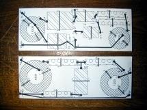
Cut Sheet #1 |
Cut Sheet #2 |

Cut Sheet #3 |
| Since
I took the time to create these "Cut Sheets", I figured
that I'd make them available to the "next guy".
Sheet #1 includes the Adire
Alignment Tempest (vented) exterior cabinet, the LCC sides, LCC
mid-chamber pieces, and a single Kit 281 internal brace (to minimize
the waste a bit).
|
Sheet
#2 contains the LCC front/back, top/bottom, Tempest internal braces,
the Kit 281 tops/bottoms, and 4 more Kit 281 internal braces.
BTW, these plans are all based on
4'x8' sheets of MDF, single thickness cabinets, and a 3/32" saw
kerf.
|
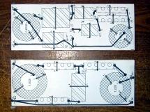
Sheet
#3 contains the Kit 281 fronts/backs, one side piece, and 3 internal
braces.
Of additional note is that if you
are not doing a full 5 speaker plus subwoofer build, you might very
well have to arrange the pieces differently to get a more efficient
use if the woof.
|
Cut Sheet #4 |

Cut Sheet #5 |

Panel Stacks |
| Sheet
#4 is easy. It contains the balance of the Kit 281 side
pieces... all seven of them.
BTW, in case you haven't figured
it out yet... The sub parts are "orange", the LCC
parts are "green", and the 281 parts are
"purple".
|
Finally,
sheet #5 only has the remaining 3 Kit 281 internal braces on it.
Now, I didn't spend a ton of time
optimizing the cut sheets, but I don't think it is possible to get
it down to 4 sheets, especially considering that the above cut
sheets do not include grill frames and a few other odds and ends.
Five sheets is probably the minimum.
|
Panels
are cut and stacked in kit form". From left to right: Kit
LCC, 4 Kit 281s, and the Adire Alignment Tempest (vented).
That table is an 8' long
commercial model, and it is just about at its max gross weight!
|
LCC Crossover Boards |
LCC Crossover Plan |
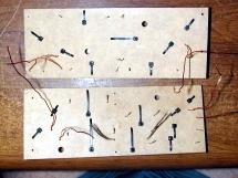
Crossover Board Drilling |
| The
Adire instructions for the Kit LCC crossover boards specify 2 boards
with dimensions of 3" x 8". I cut mine from some
scrap 1/4" "Handi-Panel" material... basically 1/4'
MDF. |
After
playing around with the printer settings just a bit, I was able to
print out the crossover placement diagrams from the instructions
(PDF file). (My printer required me to set it at 104% to get the
board outline set at exactly 3" x 8".)
Note in this image that I have
edited the layout to reflect ACTUAL component size differences,
through-hole relocations, AND through-hole sizes (in # of 32nds of
an inch).
The sizes for the lead locations
(amp, mid, tweeter, woofer) were increased some from those recorded
in the image due to the lead wire diameter being a bit larger than
anticipated.
|
Here
is just the same view after drilling the holes. I used a drill press
simply to make it easier and a bit neater. I suspect a hand drill
would work just fine.
Once again, the lead wire
locations were re-drilled to a larger size to accommodate the larger
diameter lead wire.
|
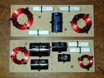
Components Secured (front) |
Components Secured (back) |

Finished Crossover (front) |
| Keeping
the layout diagram handy and properly oriented to the board, I
placed the components back on the board and secured them with small
wire ties (not the larger ones included in the kit).
Adire's instructions say to
temporarily mount them until after testing... I say,
"Wire ties are cheap! Strap 'em down." It is wayyyy easier
to test, manipulate, et al. with them strapped down.
|
Here
is the reverse side of the boards with components mounted. One thing
about using these smaller wire ties... In general, they will
snap prior to doing any damage to a component.
Note: In this image and the one
previous, you can see the 1/4" through-holes in each board.
These holes will be used to "float-mount" the boards into
the cabinet. More about that later.
|
Here
is the front view of the "finished" crossovers. i say
"finished" because they have NOT been tested yet. Yes, I
jumped the gun and soldered everything in before actually testing
them. This IS a general "No-No" in crossover building, but
I KNOW they are built according to the plan (quintuple checked
visually and electrically).
If there is a problem when I test
them in the cabinets, I'll repair/fix it then.
|

Finished Crossover (back) |
|
| Here
is the reverse side of the completed crossovers. I am NOT a
professional board assembler, so I may have not done all the
connections the "right" way. But they are all good joints.
I am actually considering building
completely new crossovers at some point with higher end
components. I would likely do one other thing differently as
well.
On all the "longer"
point-to-point connections, I will likely use good wire to make all
the connections similar to the one long run on the woofer crossover.
Simply bring the component leads straight down through the board and
solder to the wire.
|
It took me about three days to get to this point, but I was not
working full time on the project. It would have gone a LOT faster
with a larger tale saw, or a panel saw. Due to space constraints, I
have neither of those. I used a Porter Cable circular saw and a saw
board. Although you CAN get very good results using this method, it
is VERY slow. All of my cuts are within 1/32" of the
required measurement, and the vast majority of them are within
1/64".
Part two of this series s just
around the corner, so check back soon! 
|

)
)
)
)
)
)
)
)
)
)
)
)
)