| The Clamp:
(cont'd)
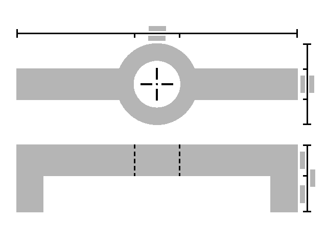
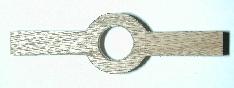
Here is the 2D plan view of version 3:
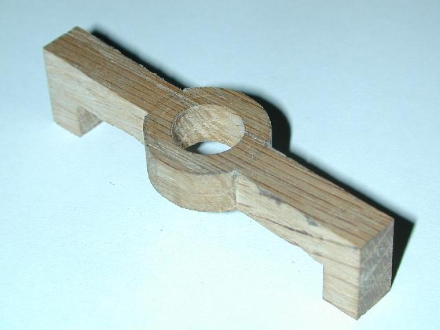
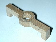
...the version 3 model (oblique):
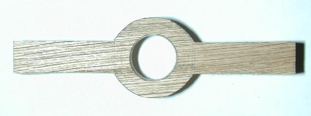
... and version 3 model (top):
|
|
I discovered that the "ears" at
the ends of the clamp were both unnecessary and actually
counter-productive, and thus eliminated them in version 3. As you will be
able to see in the work photos later in this article, the clamp is
installed over the locator pin holes on the frame. The frame is not flat
on top, thus the "ears" were not in contact with the frame
making them superfluous. In addition, they actually made it somewhat
difficult to adjust the dies with the clamp installed... not impossible,
just a bit of a challenge. In any event, deleting them from the design
eliminated both concerns. Additionally, the design change simplifies the
part, which should make it easier and more economical to produce.
If you have a good eye, you might also be
able to discern the increased diameter of the fastener boss in the center
of the clamp. I returned the diameter to the maximum dimension possible
while still maintaining clearances with the dies, pins, powder measure, et
al. This allows more material outboard of the fastener shaft and increases
the clamp's strength in the center where the tension/compression moments
are greatest when installed.
Take a look at another component...
Next...
|